mods, pre-production, Technology & Coffee
Temperature Pt. 2: Hardware
Mar
- Part 1: Getting Started
- Part 2: Hardware
- Part 3: Code
- Part 4: Reading
Temperature Part 2: Hardware
In a previous post we covered the parts and components needed to build the 3 probe RTD project. In this post, we cover how to assemble the hardware and wire the components together.
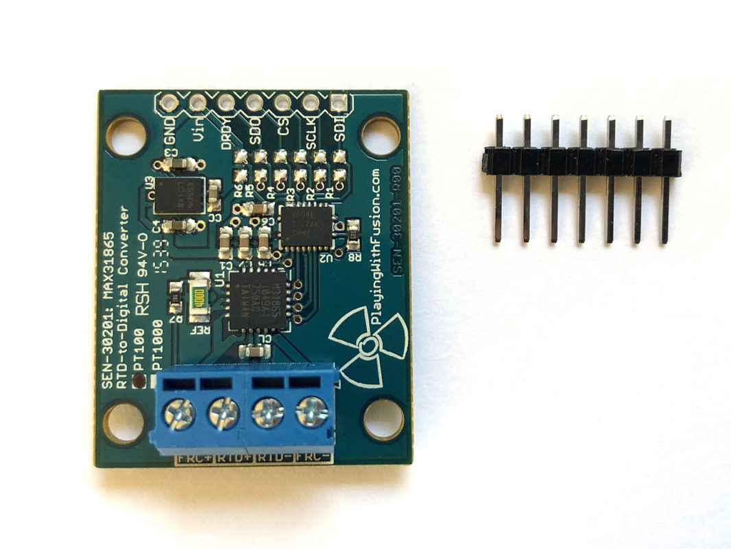
Step 1: Assemble the PWF SEN-30201-PT100 RTD Breakout Boards
A: Attach header pins to the PCB
Header pins need to be soldered onto the PWF RTD breakout board. Header pins can be used to attach Dupont cables or be used to plug the PCB directly into a breadboard. For our project, the pins should be mounted to the underside of the PCB.
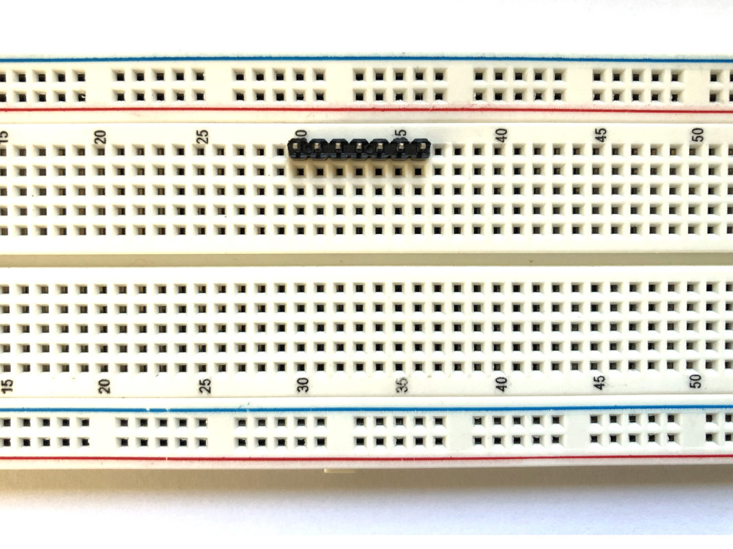
B: Insert header pins into the breadboard
Oftentimes the most challenging part of soldering is finding a way to securely hold the parts together while working. Here’s a neat trick to make this process easier. First start by inserting the header pins into the breadboard.
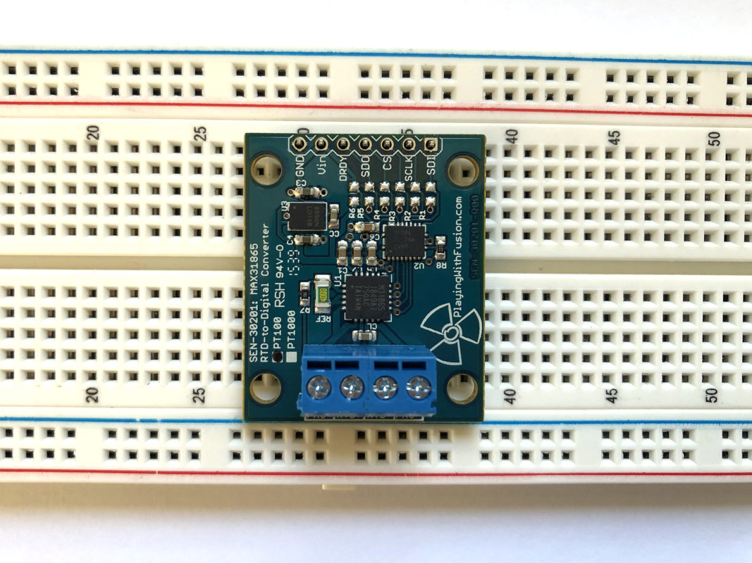
C: Place the board on top of the pins
Next place the board on top of the pins and solder in place.
D: Task complete
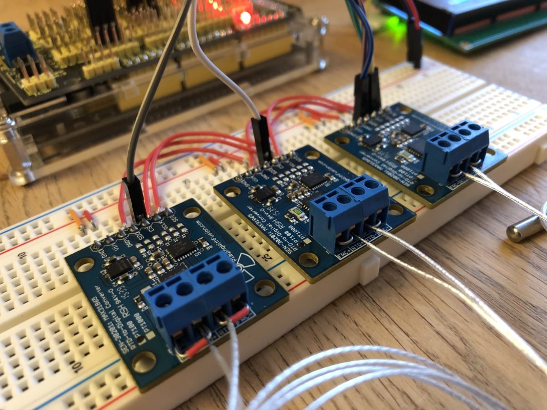
Now that you’ve finished the first, repeat the same process for the next two boards. Below is what the end result should look like.

Step 2: Wire the 3 breakout boards to the breadboard
With the 3 breakout boards now ready to go, mount them to the breadboard.
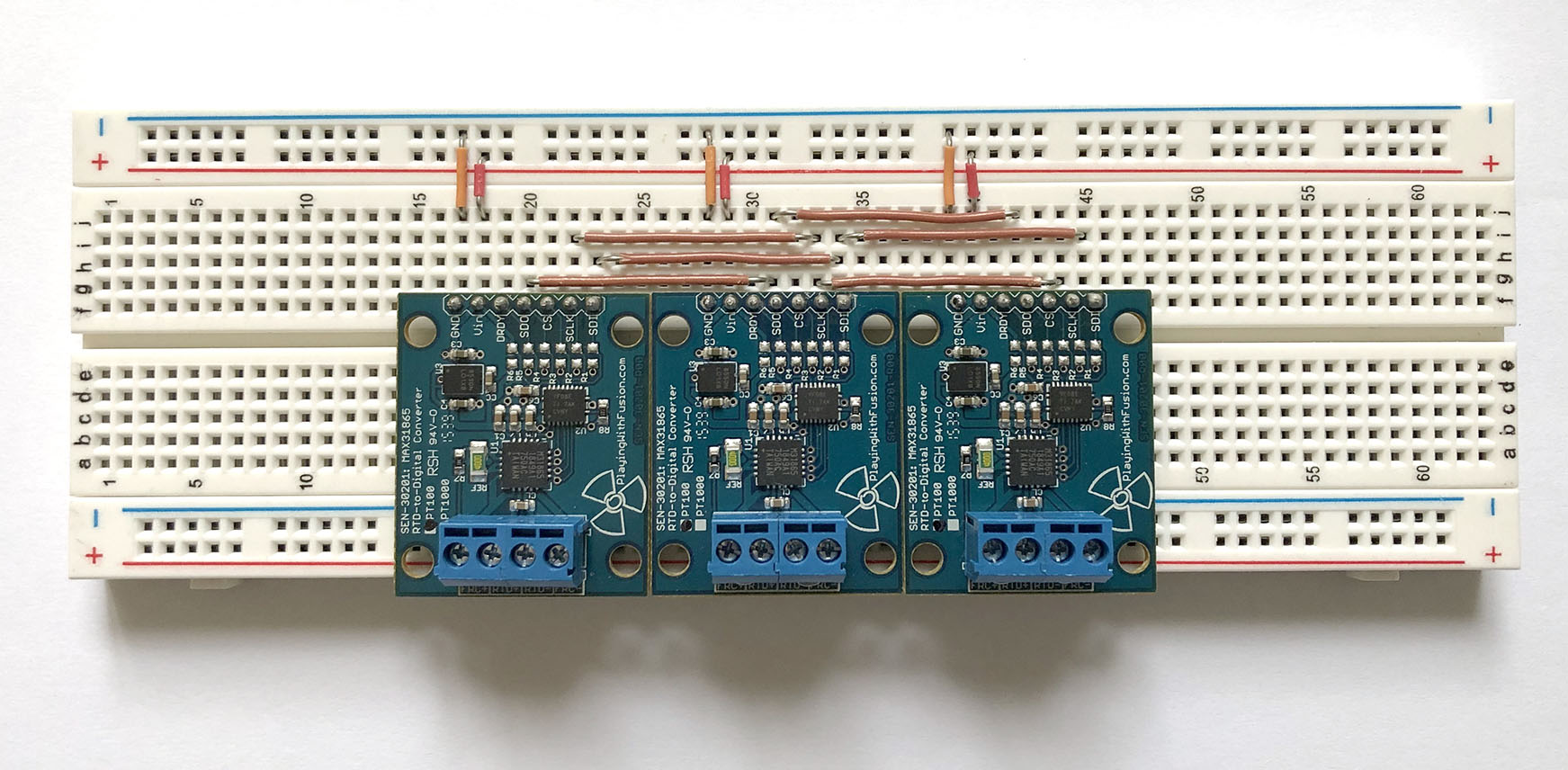
Using the jumper wires, connect the Vin and GND pins to the + / – rail as shown.
The SPI interface is shared between all 3 boards. Wire the SPI pins together using jumper cables. The following SPI pins are shared between the breakout boards and the Arduino: SDO, SLK, and SDI. Notice how the brown jumper wires form circuits between the three boards. Rows share connections and are distinguished by having sets of 5 holes.
Step 3: Wire the breadboard to the MEGA
With the 3 breakout boards mounted to the breadboard and the SPI pins wired together, begin making the connections to the Arduino MEGA with Dupont cables.
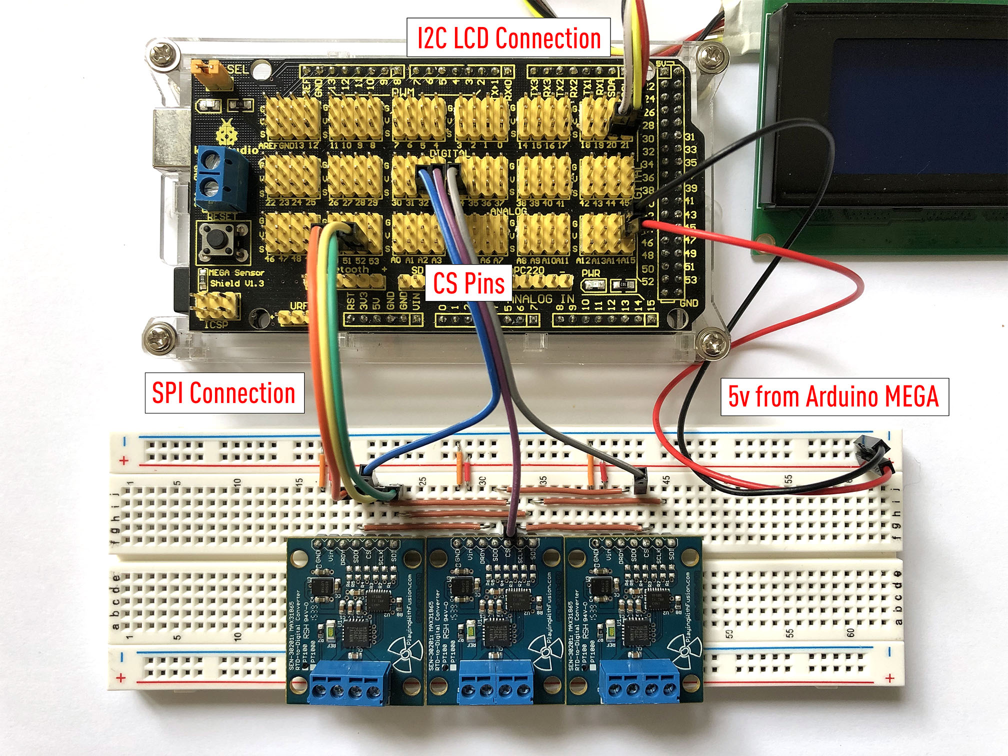
First of all, make sure the I2C LCD display is properly connected. The post on I2C LCDs shows the correct pinout for attaching this peripheral.
Next, from any open pin on the MEGA, wire +5V and GND to the +/- rail on the breadboard.
In the previous section the SPI pins between all 3 RTD boards were jumpered together. Only one connection is required between the breadboard and the MEGA for the SPI interface for all three breakout boards. Use the following pin out to connect the Arduino to the breakout boards.
Arduino --> Breakout board
MISO: pin 50 --> SDO
MOSI: pin 51 --> SDI
SCK: pin 52 --> SCLK
pin 32 --> board 1 CS pin
pin 33 --> board 2 CS pin
pin 34 — board 3 CS pin
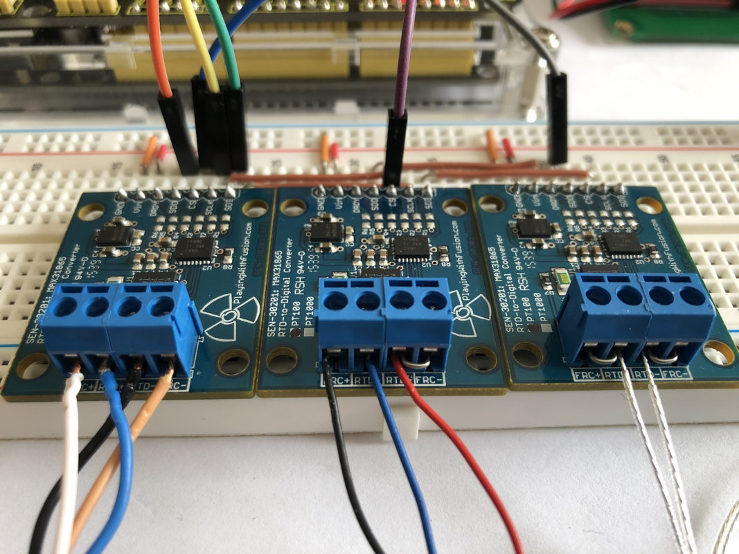
Step 4: Attach the RTD temperature probes to the breakout boards
With the wiring between the breadboard and the Arduino finished, the last step will be to connect the RTD probes to the breakout boards. RTD probes come in either 2, 3 or 4 wire configurations.
The SEN-30201-PT100 board has 4 screw terminals to accommodate all 3 types of wiring. Depending on the RTD configuration, the terminals may require jumpers. You can use the smallest breadboard jumper wire that came with your set for this task.
Most RTDs have various color coded wires which may or may not correspond to the + / – terminals called out on the board. It’s beneficial to check with the spec sheet included with your RTD to determine which color correspond to the appropriate terminal. I’ve noticed that wire color is often arbitrary and has no real standard. It may come down to trial and error to switch wires and terminals in order to determine the correct configuration.
2 wire configuration
A 2 wire RTD is attached to both the + / – terminals. A jumper will be required in between both sets of + terminals and in between the two – terminals.
3 wire configuration
For a 3 wire RTD, a single jumper is required between the two – terminals.
4 wire configuration
And finally for a 4 wire RTD, no jumper is required at all.
Additional Resources:
- Playing with Fusion’s SEN-30201-PT100 wiring diagrams
Pingback: The HG-1 Grinder – caffeinated