mods, Technology & Coffee
LCD Displays and the Serial Monitor
Mar
In a previous post I described the Arduino MEGA as an efficient and tiny mini computer. And like a tiny computer, the MEGA needs an equally efficient and tiny display in order to show the user what’s going on.
Prerequisites
- Basic understanding of programing and uploading sketches to an Arduino
In this post, we’re going to focus on two separate ways of passing data to the user from the Arduino. The first method is via the Serial Monitor which is part of the Arduino IDE and the second is to an alpha numeric liquid crystal display (LCD) screen. The goal of this post is to hook up an I2C LCD to a MEGA and write to both the display and the Serial Monitor.
Serial Communication
An Arduino can transmit and receive data bit by bit to and from a desktop computer over a serial connection. To put that into simple terms, an Arduino can talk to a desktop computer and a desktop computer can talk back. For example an Arduino can be programmed to transmit temperature readings to dedicated programs such as data plotters. Later on we’ll be playing with Processing, an open source graphics application that can be used for such tasks, but for now we’ll keep it simple.
Required Tools
- Personal Computer with Arduino IDE installed
- Arduino MEGA 2560 rev3
- I2C 20×4 LCD Display
- DuPont Wires
- Arduino MEGA sensor shield
I2C 20×4 LCD Display
For our ongoing projects we’ll be using this type of display. Think of a 20×4 LCD Display as an old-fashioned typewriter that is only able to type a maximum of 20 letters or numbers across 4 lines on a sheet of paper. While this might seem primitive in comparison to modern computer monitors, LCDs are tried and true pieces of hardware that are easy to come by and relatively inexpensive. There are smaller 16×2 LCDs but for our purposes the more data that we are able to display the better.
I2C refers to the protocol that allows the MEGA to talk to the display. SPI or serial versions of 20×4 LCDs are also available, so make sure to purchase the correct type. In general I2C hardware is slower in comparison to SPI but the protocol uses fewer pins to communicate.
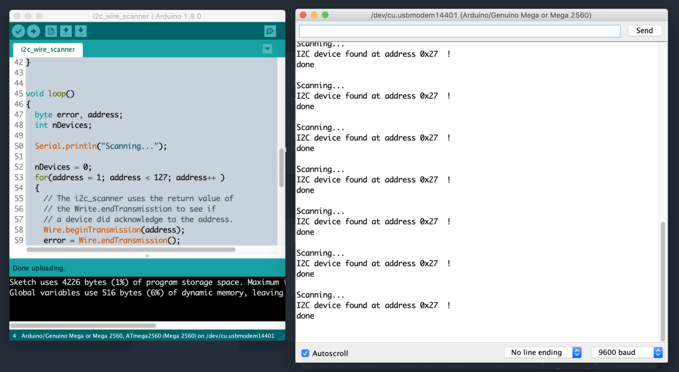
I2C is a shared bus, meaning multiple devices can share the same connection. I2C hardware addresses have to be initialized at sketch runtime to let the MCU know which peripheral to communicate with. While some hardware manufactures specify I2C addresses, it’s good practice to confirm the address on your own. By using an I2C scanner sketch and attaching one device at a time to the MCU, a peripheral’s address can be written to the Serial Monitor window.
DuPont Wires
The easiest method to connect peripherals or sensors to the MEGA is with Dupont Wires. These jumpers usually come in sets of different colors with different types of male/female connectors.
Arduino MEGA sensor shield
A shield is a card that sits directly on top of an Arduino, expanding the functionality of the device. A sensor shield breaks out the analog and digital pins into sets of 3. Each pin on the board is paired with a +5V and Ground pin. Think of a sensor shield as a conventional power strip.
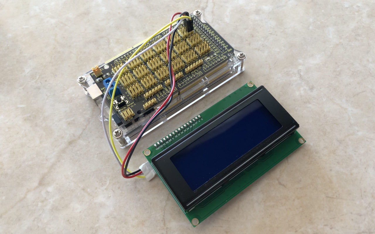
Hardware Wiring Instructions
Mounted on the back of the I2C 20×4 LCD Display should be a daughter card with 4 I2C pins.
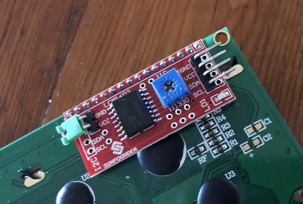
Connect the pins on the daughter card to the MEGA using the following pinout. For illustration purposes only the LCD below is a 16×2 version but the wiring is identical to a 20×4 display.
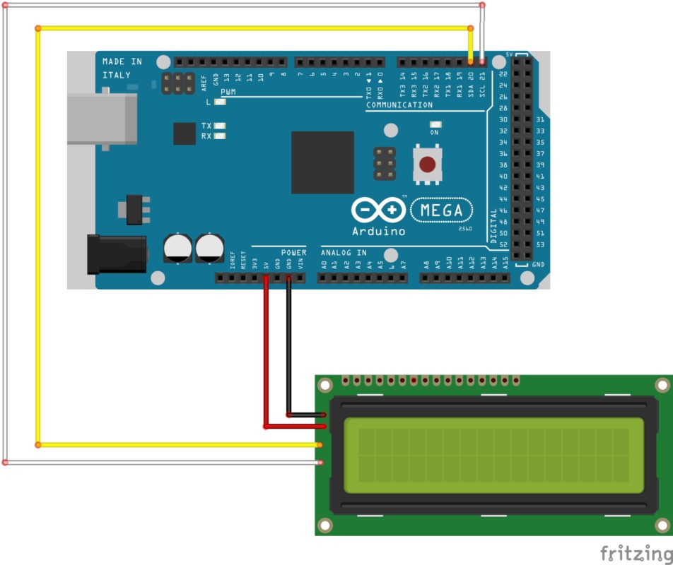
- 5V to 5V
- GND to GND
- SDA to PIN 20
- SCL to PIN 21
I2C Scanner & Hello World sketch
Once the LCD is wired to the MEGA, connect the Arduino to your personal computer. Upload and run the I2C scanner sketch mentioned above and record the I2C address written to the Serial Monitor.
Double click on the Hello World sketch below to select the code, then copy and paste into a text editor. On line 10 of the code, change the existing address to the recorded I2C address.
Save the sketch on your computer, then upload the sketch to the Arduino.
// Hello World Sketch //
/* I2C LCD SCREEN and Serial Print */
/* Craig Lyn Design Studio, 2019 */

// Libraries
#include <Wire.h>										// I2C library
#include <LiquidCrystal_I2C.h>			// I2C lcd screen


// set I2C hardware address to 0x27 and construct a 20 character / 4 line LCD
LiquidCrystal_I2C LCD(0x27, 2, 1, 0, 4, 5, 6, 7, 3, POSITIVE);

void setup()
{
	Serial.begin(9600);             	// initialize serial port, set the communication speed

	LCD.clear();											// clear the LCD screen
	LCD.begin(20,4);  								// initialize the lcd for 20 chars 4 lines, turn on backlight
	LCD.setCursor(6,0); 							// set the cursor to (CHAR #, LINE #) (0-19, 0-3)
	LCD.print("CRAIG LYN");						// write to the LCD

	LCD.setCursor(0,1);								// set the cursor again, notice the difference from line 19?
	LCD.print("    DESIGN STUDIO");
	LCD.setCursor(0,2);
	LCD.print("      ELEMENT 1");
	LCD.setCursor(0,3);
	LCD.print("        Hello World");

	Serial.println("Hello World");		// write to the Serial port, the Arduino IDE will display this text in the Serial Monitor
}


void loop()
{

}
Results
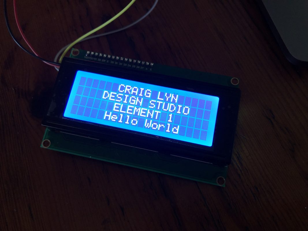
Once the sketch has been uploaded the MEGA should reboot and the following text will be displayed on the LCD screen. Experiment by changing the layout and text being written to the screen.
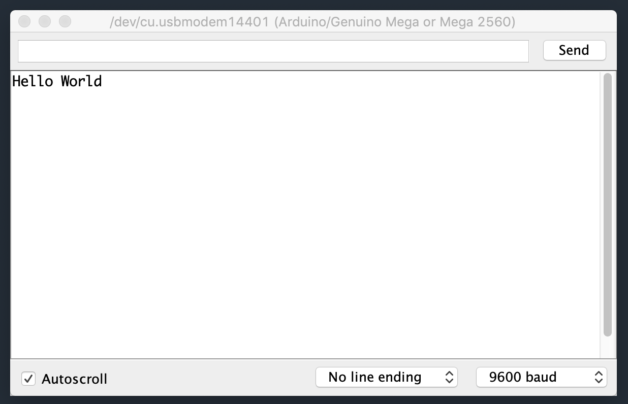
Open the Serial Monitor Window in the Arduino IDE and you should see the following text displayed. Experiment with the print() command.
Additional Resources
- Video connecting a MEGA to a 16×2 I2C Display
- Tutorial showing wiring diagrams I2C addresses
- I2C Scanner Sketch
In the next post we’re going to jump ahead and cover some more advanced subjects. We will be making a 3 channel PT100 RTD probe that can be used to take very accurate high temperature readings.