mods, news, Technology & Coffee
Temperature Pt. 3: Code
Mar
Temperature Pt. 3: Code
In the previous post we covered assembly and wiring for our 3 channel RTD sensor so by this point you should have all of the components prepped and ready to go. The goal of the current post is to go over the basics of our sketch, make some minor edits, and then upload our sketch to the Arduino MEGA.
Our sketch is designed to read input signals from each of the 3 RTD breakout boards and then calculate the resulting temperature from each probe. The temperature is then written out to both the LCD display and to the Arduino IDE Serial Monitor.
Prerequisites
- Basic understanding of programing and uploading sketches to an Arduino
- Completed the previous post on LCD Displays and the Serial Monitor
Our Sketch
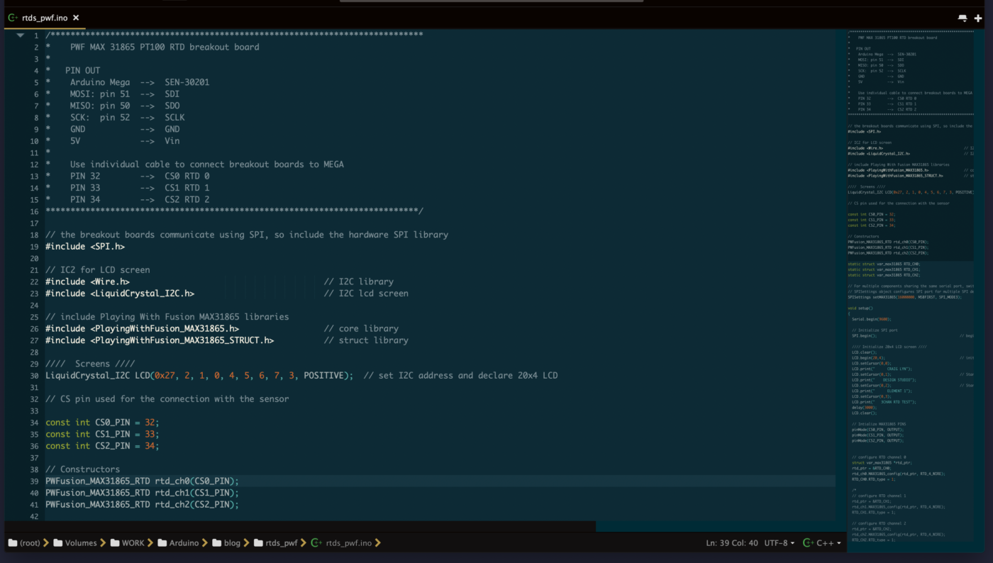
Double click the code below to highlight the text. Copy and paste the code into a text editing program. Make your edits and then save to a local hard drive.
/***************************************************************************
*		Craig Lyn Design Studio
*		3 Channel RTD sensor with PWF MAX 31865 PT100 RTD breakout board
*		3/20/19
*
*		PIN OUT
*    Arduino Mega  -->  SEN-30201
*    MOSI: pin 51  -->  SDI
*    MISO: pin 50  -->  SDO
*    SCK:  pin 52  -->  SCLK
*    GND           -->  GND
*    5V            -->  Vin
*
*    Use individual cables to connect CS pins to MEGA
*    PIN 32				 -->	CS0 RTD 0
*    PIN 33        -->  CS1 RTD 1
*    PIN 34				 -->	CS2 RTD 2
***************************************************************************/

// the breakout boards communicate using SPI so include the hardware SPI library
#include <SPI.h>

// IC2 for LCD screen
#include <Wire.h>																				// I2C library
#include <LiquidCrystal_I2C.h>													// I2C lcd screen

// include Playing With Fusion MAX31865 libraries
#include <PlayingWithFusion_MAX31865.h>              		// core library
#include <PlayingWithFusion_MAX31865_STRUCT.h>       		// struct library

////	Screens	////
LiquidCrystal_I2C LCD(0x27, 2, 1, 0, 4, 5, 6, 7, 3, POSITIVE);  // set I2C address and declare 20x4 LCD

// CS (chip select) pins used to select which breakout board is being called by the MCU
const int CS0_PIN = 32;
const int CS1_PIN = 33;
const int CS2_PIN = 34;

// Constructors
PWFusion_MAX31865_RTD rtd_ch0(CS0_PIN);
PWFusion_MAX31865_RTD rtd_ch1(CS1_PIN);
PWFusion_MAX31865_RTD rtd_ch2(CS2_PIN);

static struct var_max31865 RTD_CH0;
static struct var_max31865 RTD_CH1;
static struct var_max31865 RTD_CH2;

// Create SPI object to switch on/off communication with devices
SPISettings setMAX31865(16000000, MSBFIRST, SPI_MODE3);

void setup()
{
	// Initialize Serial port
  Serial.begin(9600);

  // Initialize SPI port
  SPI.begin();

	//// Initialize 20x4 LCD screen	////
	LCD.clear();
	LCD.begin(20,4);  																	// initialize the lcd for 20 chars 4 lines, turn on backlight
	LCD.setCursor(0,0);
	LCD.print("      CRAIG LYN");
	LCD.setCursor(0,1); 																// set cursor (CHAR, LINE)
	LCD.print("    DESIGN STUDIO");
	LCD.setCursor(0,2);
	LCD.print("      ELEMENT 1");
	LCD.setCursor(0,3);
	LCD.print("   3CHAN RTD SENSOR");
	delay(3000);
	LCD.clear();

	// Intialize CS PINS
	pinMode(CS0_PIN, OUTPUT);
  pinMode(CS1_PIN, OUTPUT);
	pinMode(CS2_PIN, OUTPUT);

	struct var_max31865 *rtd_ptr;

	// configure RTD channel 0 - PCB 1
	rtd_ptr = &RTD_CH0;
  rtd_ch0.MAX31865_config(rtd_ptr, RTD_4_WIRE);	// specify 4 wire configuration
  RTD_CH0.RTD_type = 1;

	// configure RTD channel 1 - PCB 2
	rtd_ptr = &RTD_CH1;
  rtd_ch1.MAX31865_config(rtd_ptr, RTD_3_WIRE);	// specify 3 wire configuration
  RTD_CH1.RTD_type = 1;

	// configure RTD channel 2 - PCB 3
	rtd_ptr = &RTD_CH2;
  rtd_ch2.MAX31865_config(rtd_ptr, RTD_2_WIRE); // sepecify 2 wire configuration
  RTD_CH2.RTD_type = 1;

  // give the sensors time to set up
  delay(100);
}

void loop()
{
  delay(1500);                                   // 1500ms delay... can be much faster

	// open SPI commuincation
	SPI.beginTransaction(setMAX31865);

  double tmp;
  struct var_max31865 *rtd_ptr;

  rtd_ptr = &RTD_CH0;
  rtd_ch0.MAX31865_full_read(rtd_ptr);          // Update MAX31855 readings

  rtd_ptr = &RTD_CH1;
  rtd_ch1.MAX31865_full_read(rtd_ptr);          // Update MAX31855 readings

	rtd_ptr = &RTD_CH2;
  rtd_ch2.MAX31865_full_read(rtd_ptr);          // Update MAX31855 readings


  // ******************** Print RTD 0 Information ********************
  Serial.println("RTD Sensor 0:");              // Print RTD0 header

  if (RTD_CH0.status == 0)                       // no fault, print info to serial port
  {

    // calculate RTD temperature (simple calc, +/- 2 deg C from -100C to 100C)
    // more accurate curve can be used outside that range
    tmp = ((double)RTD_CH0.rtd_res_raw / 32) - 256;
    Serial.print("TEMP = ");                    // print RTD temperature heading
    Serial.print(tmp);                          // print RTD resistance
    Serial.println(" deg C");                   // print RTD temperature heading

		// write to LCD
		LCD.setCursor(0,0);
		LCD.print("RTD 0 TEMP = ");
		LCD.setCursor(13,0);
		LCD.print("       ");
		LCD.setCursor(13,0);
		LCD.print(tmp);

  }  // end of no-fault handling
  else
  {
		// write to serial port
    Serial.print("RTD 0 FAULT: CHECK CONNECTION ");
    Serial.println(RTD_CH0.status);

		// write to LCD
		LCD.setCursor(0,0);
		LCD.print("RTD 0 FAULT: ");
		LCD.print(RTD_CH0.status);

  }  // end of fault handling


  // ******************** Print RTD 1 Information ********************
  Serial.println("RTD Sensor 1:");              // Print RTD0 header

  if(0 == RTD_CH1.status)                       // no fault, print info to serial port
  {
    tmp = ((double)RTD_CH1.rtd_res_raw / 32) - 256;
    Serial.print("TEMP = ");                    // print RTD temperature heading
    Serial.print(tmp);                          // print RTD resistance
    Serial.println(" deg C");                   // print RTD temperature heading

		// LCD
		LCD.setCursor(0,1); 																// Start at character 5 on line 0 (CHAR, LINE)
		LCD.print("RTD 1 TEMP = ");
		LCD.setCursor(13,1); 																// Start at character 5 on line 0 (CHAR, LINE)
		LCD.print("       ");
		LCD.setCursor(13,1); 																// Start at character 5 on line 0 (CHAR, LINE)
		LCD.print(tmp);
  }  // end of no-fault handling
  else
  {
    Serial.print("RTD 1 FAULT: CHECK CONNECTION ");
    Serial.println(RTD_CH1.status);

		// LCD
		LCD.setCursor(0,1); 																// Start at character 5 on line 0 (CHAR, LINE)
		LCD.print("RTD 1 FAULT: ");
		LCD.print(RTD_CH1.status);

  }  // end of fault handling


	// ******************** Print RTD 2 Information ********************
  Serial.println("RTD Sensor 2:");              // Print RTD0 header

  if(0 == RTD_CH2.status)                       // no fault, print info to serial port
  {
    tmp = ((double)RTD_CH2.rtd_res_raw / 32) - 256;
    Serial.print("TEMP = ");                    // print RTD temperature heading
    Serial.print(tmp);                          // print RTD resistance
    Serial.println(" deg C");                   // print RTD temperature heading

		// LCD
		LCD.setCursor(0,2);
		LCD.print("RTD 2 TEMP = ");
		LCD.setCursor(13,2);
		LCD.print("       ");
		LCD.setCursor(13,2);
		LCD.print(tmp);

  }  // end of no-fault handling
  else
  {
    Serial.print("RTD 2 FAULT: CHECK CONNECTION ");
    Serial.println(RTD_CH2.status);

		// LCD
		LCD.setCursor(0,2);
		LCD.print("RTD 2 FAULT: ");
		LCD.print(RTD_CH2.status);

  }  // end of fault handling

	// write carriage return to serial port
	Serial.println("");

	// close SPI communication
	SPI.endTransaction();
}
Download the Libraries
The SEN-30201 breakout boards require custom libraries from Playing with Fusion that are not part of the normal Arduino distribution. These libraries can be downloaded from Github and installed manually. Be sure to download and install these libraries prior to attempting to compile and upload our sketch to the Arduino.
*    PIN 33        -->  CS1 RTD 1
*    PIN 34				 -->	CS2 RTD 2
***************************************************************************/

// the breakout boards communicate using SPI so include the hardware SPI library
#include <SPI.h>

// IC2 for LCD screen
#include <Wire.h>																				// I2C library
#include <LiquidCrystal_I2C.h>													// I2C lcd screen

// include Playing With Fusion MAX31865 libraries
#include <PlayingWithFusion_MAX31865.h>              		// core library
#include <PlayingWithFusion_MAX31865_STRUCT.h>       		// struct library

////	Screens	////
LiquidCrystal_I2C LCD(0x27, 2, 1, 0, 4, 5, 6, 7, 3, POSITIVE);  // set I2C address and declare 20x4 LCD
Edit the sketch
Two parts of the sketch will require editing: the I2C address for the LCD and the type of RTD being used with the breakout boards.
#include <PlayingWithFusion_MAX31865_STRUCT.h>       		// struct library

////	Screens	////
LiquidCrystal_I2C LCD(0x27, 2, 1, 0, 4, 5, 6, 7, 3, POSITIVE);  // set I2C address and declare 20x4 LCD

// CS (chip select) pins used to select which breakout board is being called by the MCU
const int CS0_PIN = 32;
- The I2C address for the LCD is defined in the highlighted line. The sketch is currently using the hardware address of 0x27. Please refer to the post on LCD Displays and the Serial Monitor for more information on reading and correctly setting the I2C address of an LCD display.
struct var_max31865 *rtd_ptr;

	// configure RTD channel 0 - PCB 1
	rtd_ptr = &RTD_CH0;
  rtd_ch0.MAX31865_config(rtd_ptr, RTD_4_WIRE);	// specify 4 wire configuration
  RTD_CH0.RTD_type = 1;

	// configure RTD channel 1 - PCB 2
	rtd_ptr = &RTD_CH1;
  rtd_ch1.MAX31865_config(rtd_ptr, RTD_3_WIRE);	// specify 3 wire configuration
  RTD_CH1.RTD_type = 1;

	// configure RTD channel 2 - PCB 3
	rtd_ptr = &RTD_CH2;
  rtd_ch2.MAX31865_config(rtd_ptr, RTD_2_WIRE); // sepecify 2 wire configuration
  RTD_CH2.RTD_type = 1;

  // give the sensors time to set up
  delay(100);
- In the previous post we learnt how to hook up 4, 3, and 2 wire RTDs to the breakout boards. In the highlighted sections of code, the type of RTD attached to each board is called out. Depending on the type of RTD being used (4, 3, or 2 wire), change the code to reflect the configuration.
- Sample code for the Playing with Fusion SEN-3012 board includes a more in depth explanation to the additional functionality of the libraries and can be downloaded directly from GitHub.
Upload the Code
Save the sketch to your local hard drive using any name with the suffix .ino making sure not to use any spaces in the name. Also be sure to save the sketch in a folder with the same name as the sketch. Upload the code to the MEGA.
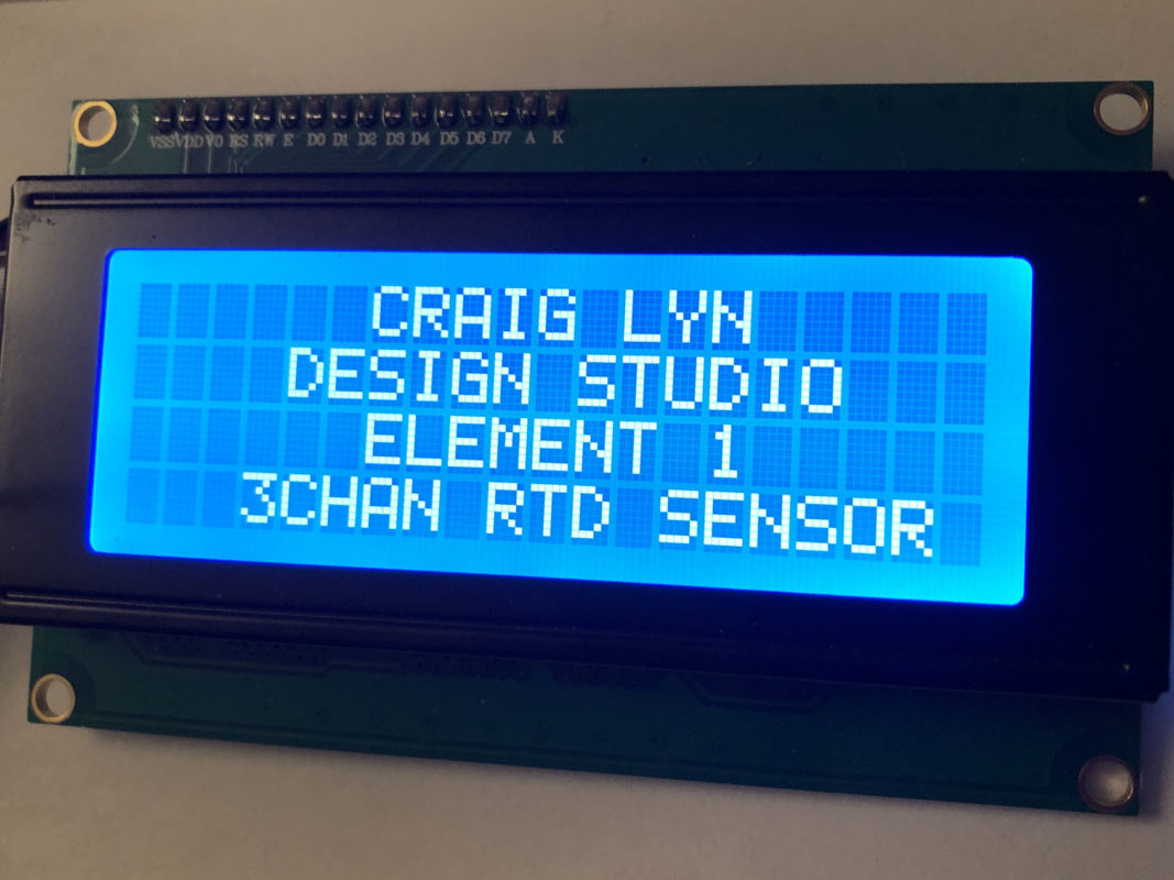
If you’ve done everything correctly, you should see the following displayed on the LCD for a few seconds before the screen switches over to temperature readings.
Additional Resources
- Playing with Fusion GitHub Repository for SEN-30201-PT100 libraries
- Arduino SPI Library
- Using multiple SPI devices on the same bus with SPISettings
- How to install libraries in the Arduino IDE
- Adafruit tutorial for Arduino IDE Serial Monitor